Instrument Description
Telescope and Site
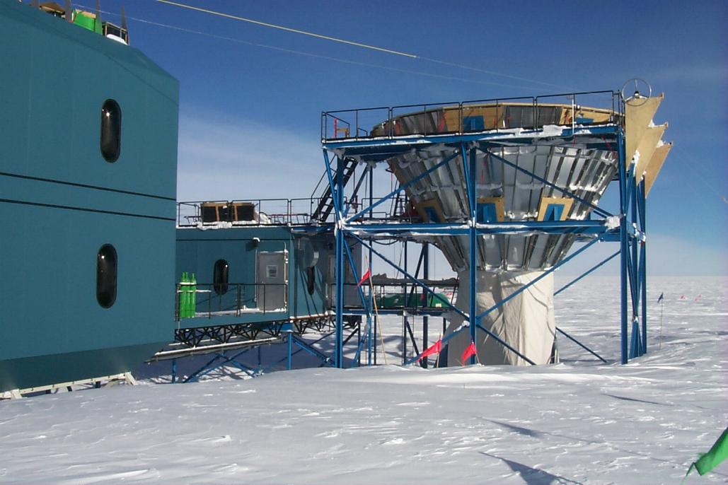
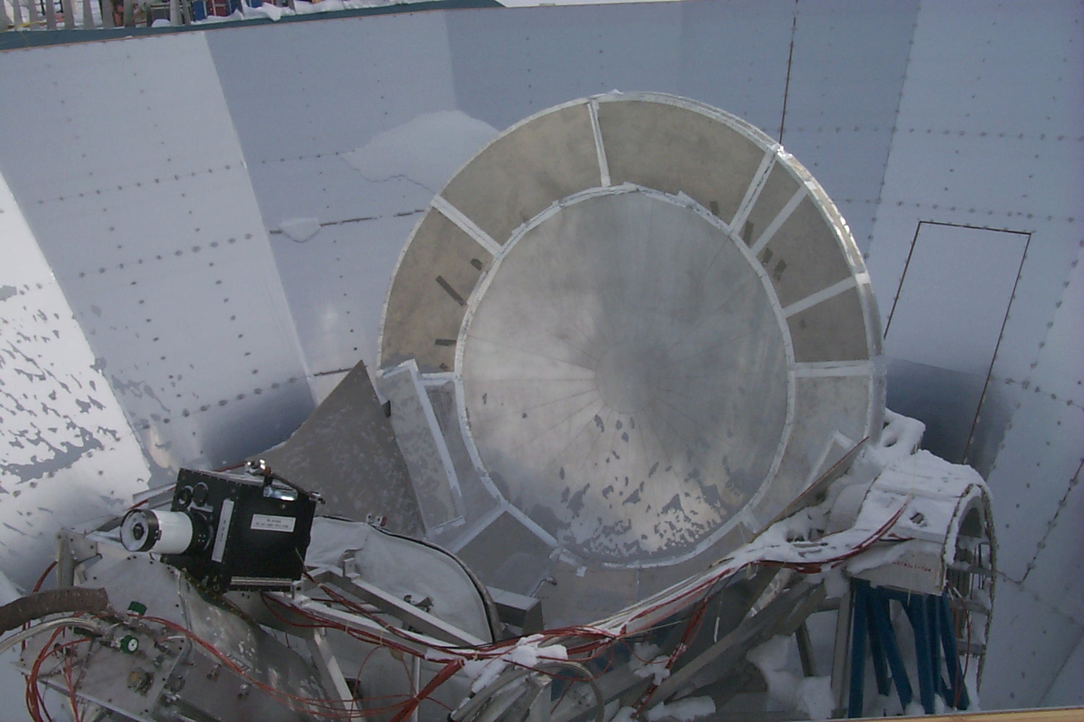
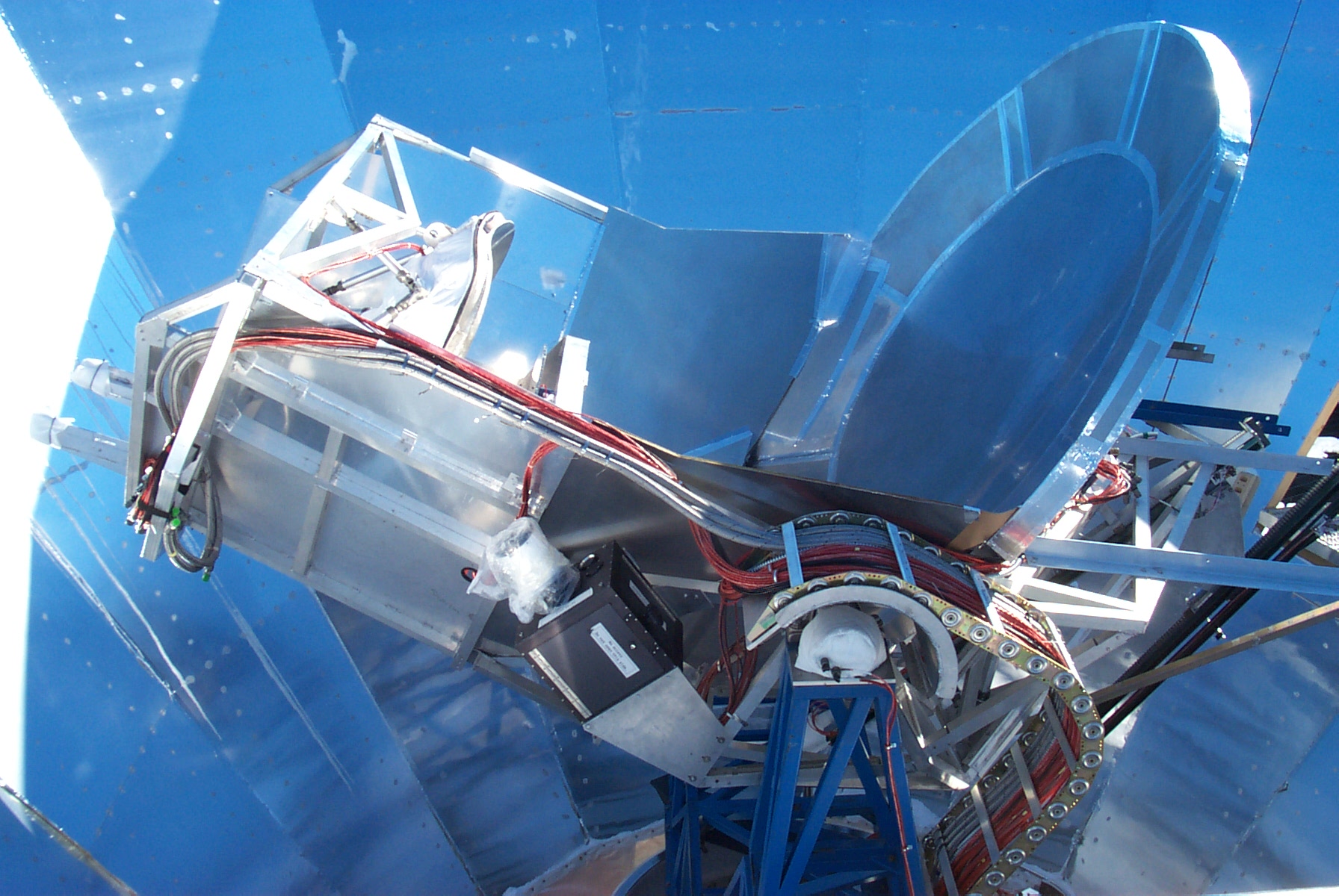
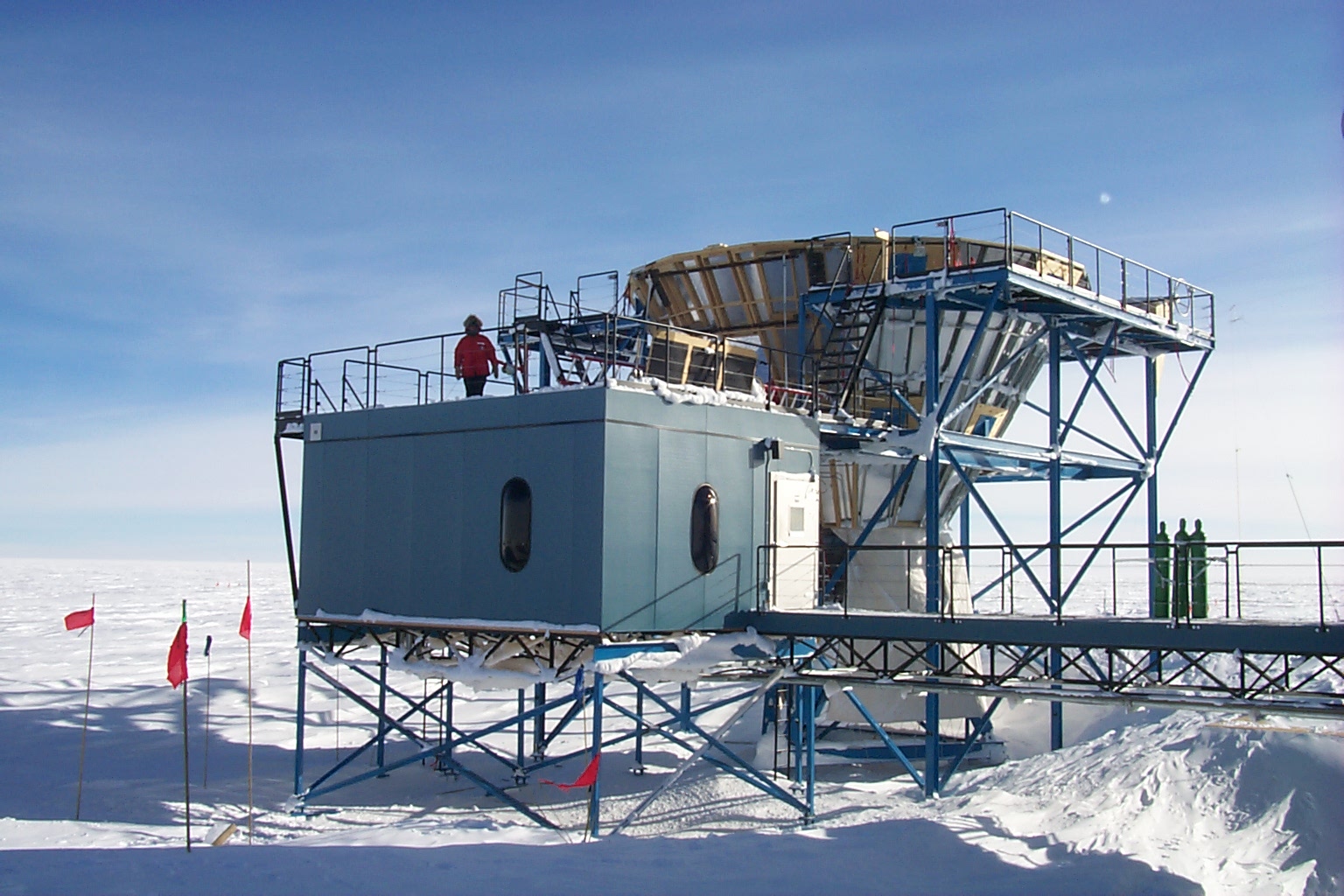
These figures show the Viper telescope at South Pole Station.
Viper, which sits within the shown conical ground shield, is an
off-axis gregorian reflector with a 2 m primary mirror and an
additional 0.5 m radius of skirt. It has a chopping tertiary at
an image of the primary in order to sweep the beams on the sky.
The next figure shows the measured variance in atmospheric
opacity at Mauna Kea (Hawaii), Chajnantor (Chile), and the South
Pole. The Viper telescope is located at the South Pole, which
has a pressure elevation of ~11,000’ and is arguably the
best site on the planet for millimeter wave astrophysics. Winter
observations with the ACBAR instrument will be detector noise
dominated.
ACBAR Cryostat
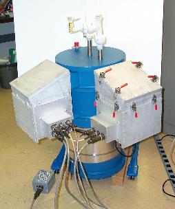
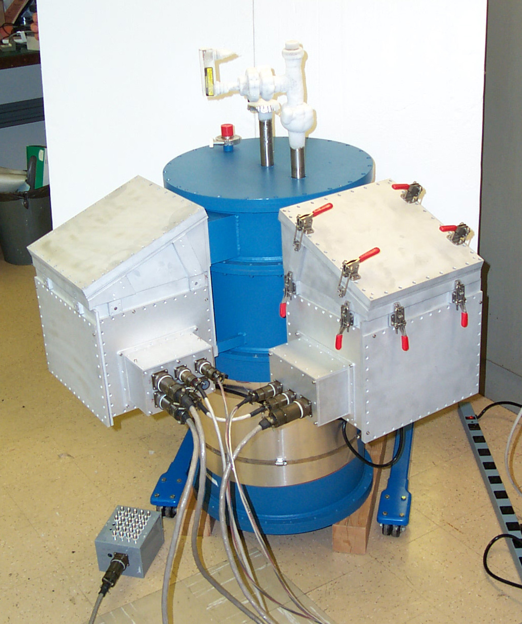
This photo is the fully assembled ACBAR instrument being tested
in Berkeley. The detectors are deep inside the blue liquid
helium cryostat. The electronics which amplify the signals from
the detectors and control and monitor cryogenics are housed in
the two rugged aluminum boxes. The ACBAR liquid helium cryostat
maintains the receiver package at a temperature of 4 K for four
days between cryogen fills. A liquid He3 sorption
refrigerator cools the detectors to 240 mK.
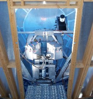
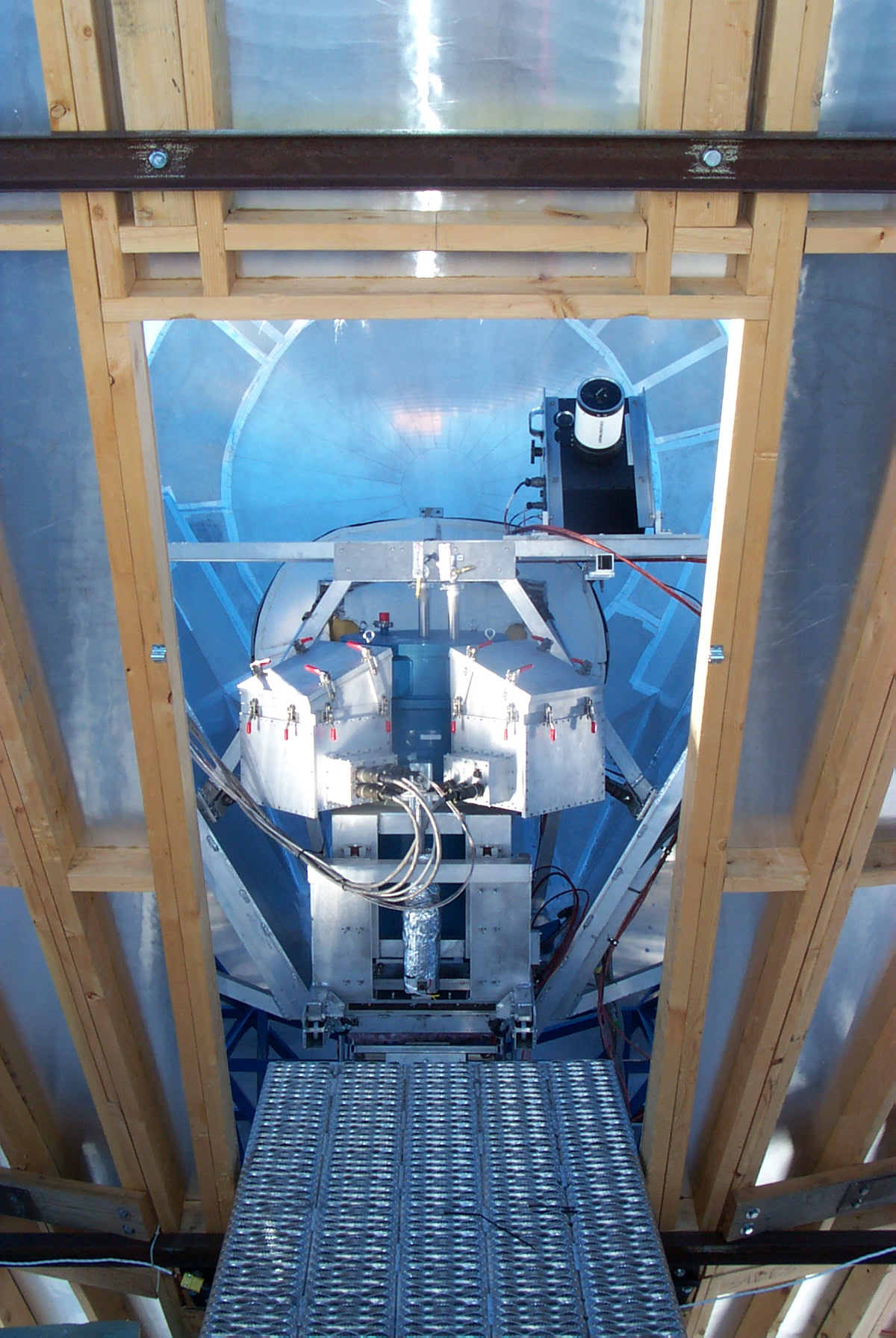
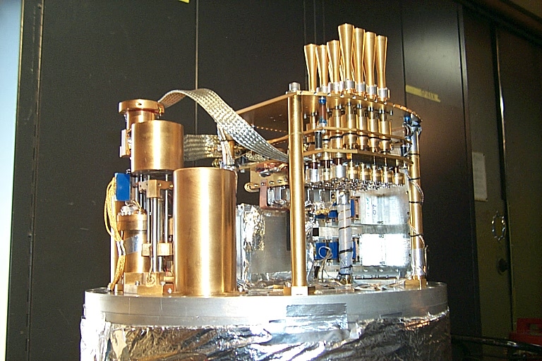
The next photo is the fully-assembled ACBAR receiver mounted on the
Viper telescope at the South Pole in December 2000.
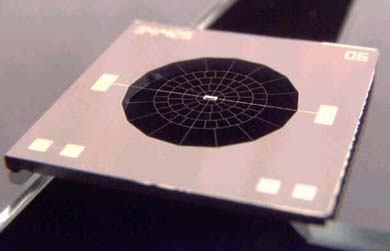
Micromesh Bolometers
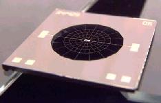
The bolometers used in ACBAR are SiN micromesh spiders with NTD
germanium thermistors. These bolometers have a low cross
section to cosmic rays and are very fast due to reduced heat
capacity. They are similar to the detectors baselined for the
Planck HFI. They were built in the Micro Lab at JPL.
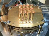
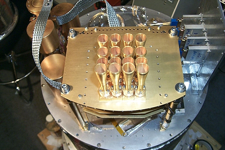
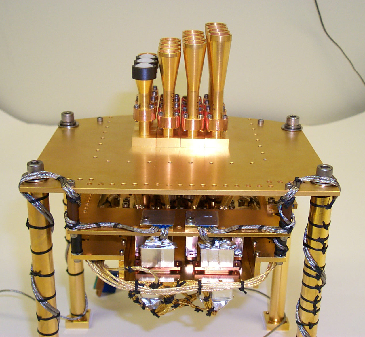
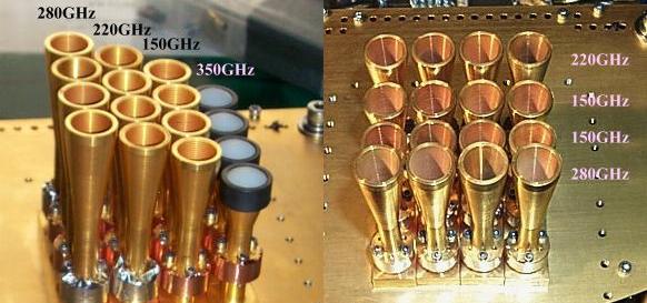
16 Element 250mK Array
The ACBAR bolometer array consists of four rows with four
frequencies in each row. The feeds have been designed to give
matched 4’ beam sizes at all frequencies. The array is
swept across 3° of sky at 1 Hz giving complete frequency
coverage on each strip of sky. The first picture shows the beam
forming optics, filters and detectors of the ACBAR array. The
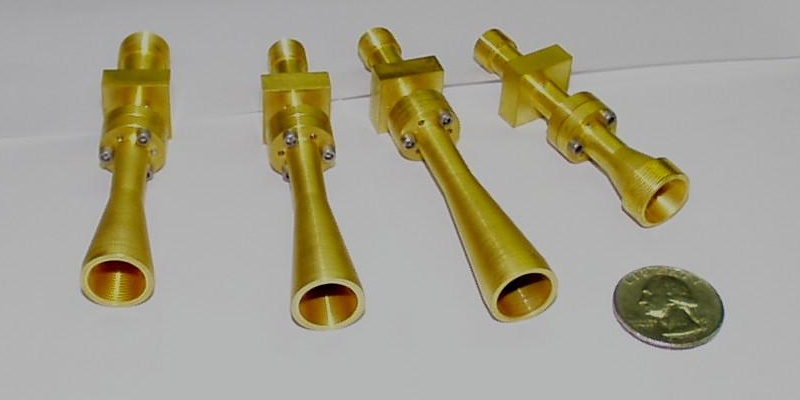
following pair of pictures show the individual feed horns.
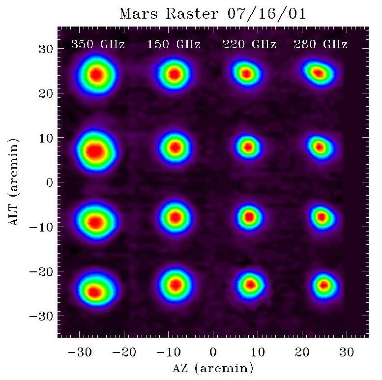
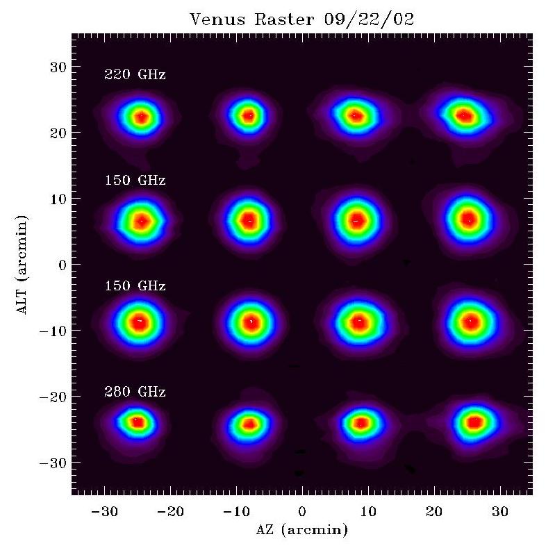
The following two images are the beam maps using Mars and Venus as targets.
The left image is a plot of the beam pattern of each of the 16
pixels of the ACBAR receiver measured by mapping Mars. The
receiver frequencies corresponding to each column are (from left
to right): 345 GHz, 150 GHz, 219 GHz, and 274 GHz. The measured
FWHM of the beam agrees well within predictions, with beams
ranging from 3.5’ to 4.5’ in the 150, 274 and 219
channels. The right image is the same thing but using Venus
instead of Mars.
Measured Performance of ACBAR
| Frequency Band (GHz) |
150 |
219 |
274 |
| Bandwidth (GHz) |
29 |
30 |
50 |
| Number of Detectors |
8 |
4 |
4 |
| Optimal Efficiency (%) |
40 |
32 |
31 |
| Beam Size (arcminute FWHM) |
4.8 |
3.9 |
3.9 |
| Detector NEP (10-17 W Hz-1/2) |
8.2 |
7.4 |
16.2 |
| NETRJ (μK s1/2) |
180 |
200 |
270 |
| NETCMB (μK s1/2) |
300 |
590 |
1470 |
| NEy (10-4 s1/2) |
1.1 |
N/A |
5.5 |
| NEFD (mJ s1/2) |
110 |
140 |
290 |
Lastly, here's a bit of graffiti found on the dewar...
|