Instrument Description
Telescope and Site
 Anisotropy observations were made with the BIMA array in Hat Creek
California. The BIMA antennae are 6.1 m in diameter and produce
a 6.6' primary beam at 28.5 GHz.
Anisotropy observations were made with the BIMA array in Hat Creek
California. The BIMA antennae are 6.1 m in diameter and produce
a 6.6' primary beam at 28.5 GHz.
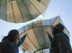
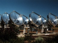 In order to maximize the sensitivity of the BIMA array to
objects on the sky as large as a cluster of galaxies, the
telescopes are placed in a compact configuration (left). The
compact configuration is sensitive to structure on the sky that
is 2 arcminutes in diameter and smaller. In this configuration,
the telescopes are close enough to touch.
In order to maximize the sensitivity of the BIMA array to
objects on the sky as large as a cluster of galaxies, the
telescopes are placed in a compact configuration (left). The
compact configuration is sensitive to structure on the sky that
is 2 arcminutes in diameter and smaller. In this configuration,
the telescopes are close enough to touch.
HEMT Receivers
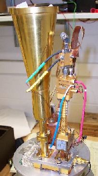
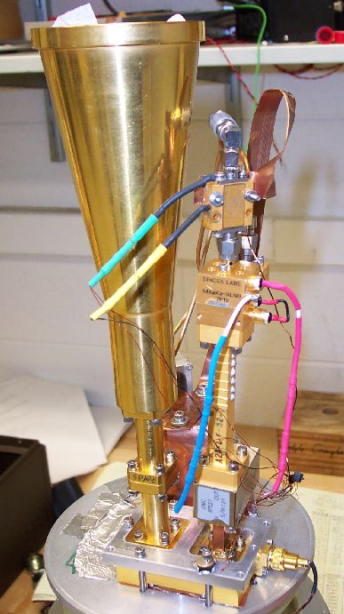
 A typical receiver used in anisotropy observations is shown to
the right and to the left. The first component in the receiver
is the corrugated feed horn. The incoming signal passes through
the corrugated field horn into the first active component in the
receiver, the HEMT amplifier. The HEMT amplifier is an
integrated circuit of transistors and other discrete components
that is designed to operate at cm wavelengths. This amplifier
is sensitive to radiation at 1 cm, or 26-36 GHz, and amplifies
the signal by a factor of 10,000. This step effectively
eliminates any instrumental noise from the receiver components
that lie behind the HEMT. The signal from the HEMT amplifier is
then down converted to the GHz range with a local oscillator and
mixer. The down conversion stage is neccessary in order to
carry the signal from the telescopes to the correlator room with
minimal attenuation from the cables. The system temperature of
the receiver is approximately 12-18 K, while the additional
loading from the sky and telescope is expected to be 30-40 K,
depending on weather conditions and telescope elevation.
A typical receiver used in anisotropy observations is shown to
the right and to the left. The first component in the receiver
is the corrugated feed horn. The incoming signal passes through
the corrugated field horn into the first active component in the
receiver, the HEMT amplifier. The HEMT amplifier is an
integrated circuit of transistors and other discrete components
that is designed to operate at cm wavelengths. This amplifier
is sensitive to radiation at 1 cm, or 26-36 GHz, and amplifies
the signal by a factor of 10,000. This step effectively
eliminates any instrumental noise from the receiver components
that lie behind the HEMT. The signal from the HEMT amplifier is
then down converted to the GHz range with a local oscillator and
mixer. The down conversion stage is neccessary in order to
carry the signal from the telescopes to the correlator room with
minimal attenuation from the cables. The system temperature of
the receiver is approximately 12-18 K, while the additional
loading from the sky and telescope is expected to be 30-40 K,
depending on weather conditions and telescope elevation.
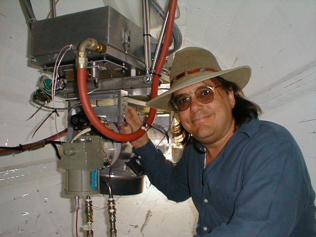
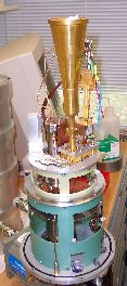
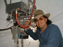
The lower figure shows Marshall Joy sitting inside the cabin of
one of the BIMA telescopes. The receiver is mounted inside the
cabin and directly behind the primary dish of the telescope.
BIMA Correlator
The correlator is the computer that retrieves the signal from
the telescopes and computes the visibilities for each pair of
telescopes. The resulting visibilities are a representation of
the data in the fourier plane as opposed to the image plane.
The signal from the telescopes arrives at the correlator with
a bandwidth of 800 MHz, centered at a frequency
of 500 MHz. There are several
modes available with the BIMA correlator that determine the
number and the resolution of spectral channels. Since the
frequency spectrum of the SZ effect is relatively flat over
this frequency range,
we choose the mode that maximizes bandwidth at the expense
of spectral resolution. This mode utilizes the full 800 MHz of
bandwidth distributed over 8 wideband channels.
The correlator multiplies the signal from every pair of
telescopes and performs a two bit digitization. The signal is
time averaged over an interval of 50 seconds and then written to
disk for data analysis. The data can be imaged by performing a
two dimensional fourier transform on the visibilities with the
analysis package, MIRIAD, provided by
the staff from BIMA. However, the visibility data itself
carries all the essential information for the anisotropy
analysis. All estimates of CMB anisotropy are derived directly
from the visibility plane.
|